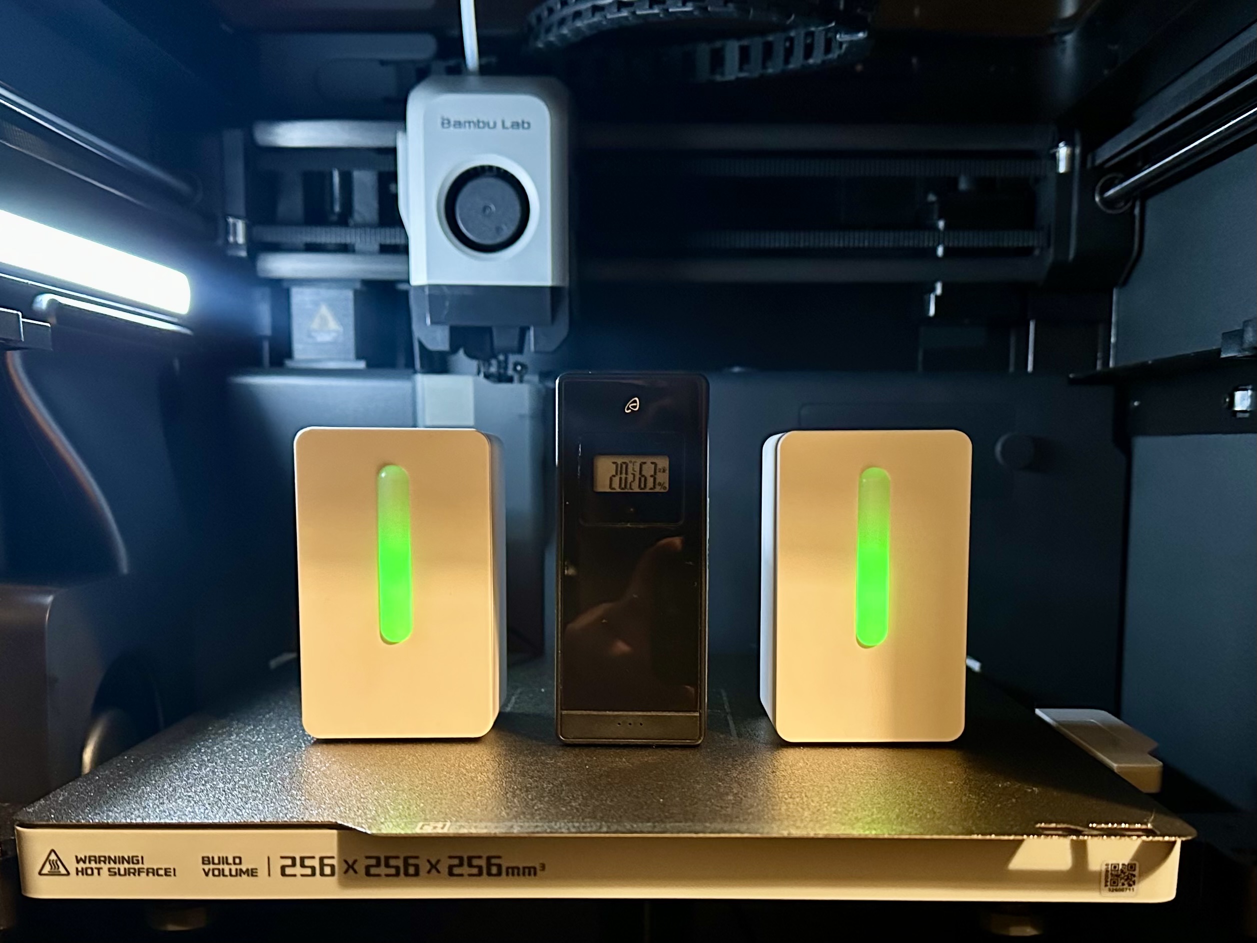
After making a few IKESP-Air air quality units an interesting issue became apparent. Due to the heat given off by the D1 Mini, the internal temperature of the unit was consistently a few degrees higher than the ambient temperature of the room in which the device was placed. This is honestly to be expected, airflow through the box is slow, the board sits at the top of the unit as does the BME280, and the heat has to go somewhere. If we want accurate room readings then, we need to account for this.
Temperature
So how do we account for the variance in temperature? It seems logical that the temperature difference would be reasonably linear across the range of temperatures we can expect to see, as the power consumption of the D1 Mini should be very consistent. Verifying that is simple enough. Take the device, put it somewhere we can control the temperature, and record the offset between its onboard temperature sensor, and a known good reading. As this is primarily intended for indoor use, a range of 0-40 °C seems sensible for comparison. Taking lower temperature measurements is easy, simply stick the sensor in the fridge and let it equilibrate. Higher temperatures may be a little more difficult to do here in the currently cold and damp autumn of the UK. Using an oven is a poor idea unless you would like your device to be a little more surrealist in its styling than the standard unit, not to mention that the temperature control of most ovens is measured in the 10s of degrees. Thankfully, I have the perfect appliance for the task. Enter the enclosed 3D printer. With a bed that heats to 100 °C, getting the internal temperature to around 40 °C should be simple enough, as should getting a good number of readings between room temperature and that point. The last thing we need is a known good sensor for comparison. I settled on an old temperature and humidity sensor that I already had, but even a cheap thermometer should do.
Confirming the Relationship
I decided to start by measuring 2 of the recently produced units. First, taking a reading at room temperature, then sticking it in the fridge for a few hours, followed by a spell in the printer. The results confirmed my earlier suspicions, that the relationship was linear, and device specific.
Calibrating the Sensor
Now that was confirmed, calibrating the temperature sensor was easy. ESPHome has a very useful function, calibrate_linear, which allows simply entering the measured values along with the correct ones, and having it produce its own correction factors.
filters:
     - calibrate_linear:
         method: least_squares
         datapoints:
           # Map 0.0 (from sensor) to 1.0 (true value)
           - 0.0 -> 1.0
           - 10.0 -> 12.1
There are 2 “methods” that can be picked from. The exact method plots a series of straight lines between consecutive points, whereas least_squares uses a least squares fit analysis to fit a single straight line to all provided data points. Both methods require a minimum of 2 data points, though more are recommended.
Should you need it, ESPHome also offer the similarly defined calibrate_polynomial filter which allows calibration according to a polynomial curve of a specified order, which must be provided at least 3 data points.
Implementing this isn’t as simple as just adding the filter to the BME280_temperature sensor in the ESPHome device configuration file, as we require the internal device temperature to provide the operating temperature to the CCS811 sensor. Instead, we create a new sensor using the template platform. Using a lambda here to report the temperature of the sensor allows us to apply any other mathematical operations we should like to the reported values, though in this case we need only report the state.
- platform: template
  name: Room Temperature
  id: corr_temp
  lambda: |-
    return (id(bme_temp).state);
  filters:
     - calibrate_linear:
         method: least_squares
         datapoints:
           # Map 0.0 (from sensor) to 1.0 (true value)
           - 14.7 -> 8.7
           - 26.1 -> 19.9
           - 31.1 -> 25.1
           - 36.2 -> 29.9
           - 44.5 -> 38.3
  unit_of_measurement: °C
We can now see both the internal temperature of the device, along with the corrected room temperature value, in Home Assistant.
Humidity and Dew Point
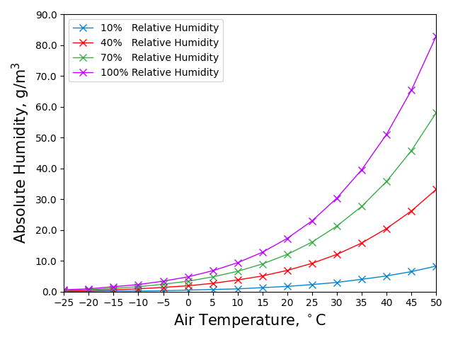
The BME280 is a combination humidity, temperature, and pressure sensor. We’ve now accounted for the difference in temperature, however we are missing a key part of the puzzle. The relative humidity which the BME280 reports is correct only for the temperature at which it is recorded, in this case the internal temperature of the device. To understand why, we first have to understand what relative humidity is. In simple terms, the relative humidity is the amount of water that is dissolved into the air, as a percentage of the maximum amount of water that could be dissolved into the air. This varies with the air temperature, as warmer air can hold a greater mass of water than cooler air of the same absolute humidity (the mass of water in a given volume of air). We can see evidence of this in our daily lives, such as the formation of dew on grass overnight as the air cools and drops below the aptly named dew point, the temperature at which moisture will begin to condense out of air of a given absolute humidity, in other words where the relative humidity reaches 100%. This same process is what causes water droplets to form on the cool surface of a mirror when you shower. In the figure below, it is clear that the mass of water in the air for a relative humidity of 100% at 20 °C is less than the absolute humidity at 40% RH at 40 °C.

The relationship between temperature and relative humidity is far more complex than a simple linear relationship, but thankfully is well understood. In order to correct the relative humidity to the new temperature, we can convert from the internal relative humidity and temperature to either the dew point or absolute humidity, then back to the relative humidity at the calculated external temperature. As the dew point would be a useful value to have anyway, I decided to use that for the conversion, and expose the dew point as its own sensor to Home Assistant.
Considering the temperature and humidity ranges we aim to work over, we can use the August-Roche-Magnus approximation to relate the dew point, relative humidity, and temperature:
$$ RH = 100 \times e^{\frac{17.625 \times T_{Dew}}{243.04 + T_{Dew}}-\frac {17.625 \times T_{Room}}{243.04+T_{Room}}} $$
Rearranging this, we can calculate the dew point using:
$$ T_{Dew} = 243.04 \times \frac{ \ln \left( \frac{RH}{100} \right) + \frac{17.625 \times T_{Room}}{243.04 + T_{Room} }}{17.625 - \ln \left( \frac{RH}{100} \right) - \frac {17.625 \times T_{Room}}{243.04 + T_{Room}})} $$
For completion, this is the equation to convert a known RH and dew point to a current temperature, though it isn’t needed for this project:
$$ T_{Room} = 243.04 \times \frac{\frac{17.625 \times T_{Dew}}{243.04 + T_{Dew} } - \ln \left( \frac{RH}{100} \right)}{17.625 - \ln \left( \frac{RH}{100} \right) - \frac {17.625 \times T_{Dew}}{243.04 + T_{Dew}})} $$
Adding the sensors to ESPHome
This can be done in ESPHome by creating 2 more template sensors, and using lambdas:
- platform: template
  name: Dew Point
  id: dew_point
  lambda: |-
    return (243.04*(log(id(bme_humi).state/100)+((17.625*id(bme_temp).state)/(243.04+id(bme_temp).state)))/
    (17.625-log(id(bme_humi).state/100)-((17.625*id(bme_temp).state)/(243.04+id(bme_temp).state))));
  unit_of_measurement: °C
- platform: template
  name: Humidity
  lambda: |-
    return (100*(exp((17.625*id(dew_point).state)/(243.04+id(dew_point).state))/
    exp((17.625*id(corr_temp).state)/(243.04+id(corr_temp).state))));
  unit_of_measurement: "%"
The Calibration Process
In order to make it easy for the friends who already have or will soon receive these units, a simple order of operations for calibrating them is essential. Happily, once the temperature is calibrated everything else will self-correct. There are effectively 2 choices for how to approach this. I could insert the above code into the configuration file, comment it out, and have them perform the required measurements for the calibration process and uncomment the sections once they have data points inserted into the temperature correction, or I can provide some example values that will be close to the correct ones, but will need to be replaced to ensure best accuracy of the devices.
I settled upon the second option, as should anyone fail to perform the temperature compensation, the values they see should still be more accurate than they would otherwise have been. Thus, the correct calibration process is:
- Power on and allow the IKESP-Air to normalise to room temperature, along with a known-good thermometer. Record the value of the thermometer alongside the internal temperature reading of the IKESP-Air sensor
- Place both the thermometer and IKESP-Air into the refrigerator, with the door closed, whilst ensuring power is still connected. Allow them both to reach a stable temperature reading and again record the thermometer and IKESP-Air internal temperature.
- Remove both devices from the fridge, and place them in a warm spot, preferably between 30-40 °C, and allow them to normalise once more. Record the values as in the previous 2 steps.
- (Optional) You can record as many extra data points as you like above the minimum of 3.
- In ESPHome, edit the IKESP-Air device configuration and replace the existing values in the
filterssection at the bottom of the configuration file (see below for an example). Take care to ensure they are inserted into the correct columns, with the internal temperature on the left, and the room temperature on the right.
- platform: template
  name: Temperature #$friendly_name Temperature
  id: corr_temp
  lambda: |-
    return (id(bme_temp).state);
  filters:
   - calibrate_linear:
      method: least_squares
      datapoints:
      # Internal Temp -> Room Temp
        - 14.7 -> 8.7    # Replace
        - 31.1 -> 25.1   # these
        - 44.5 -> 38.3   # values