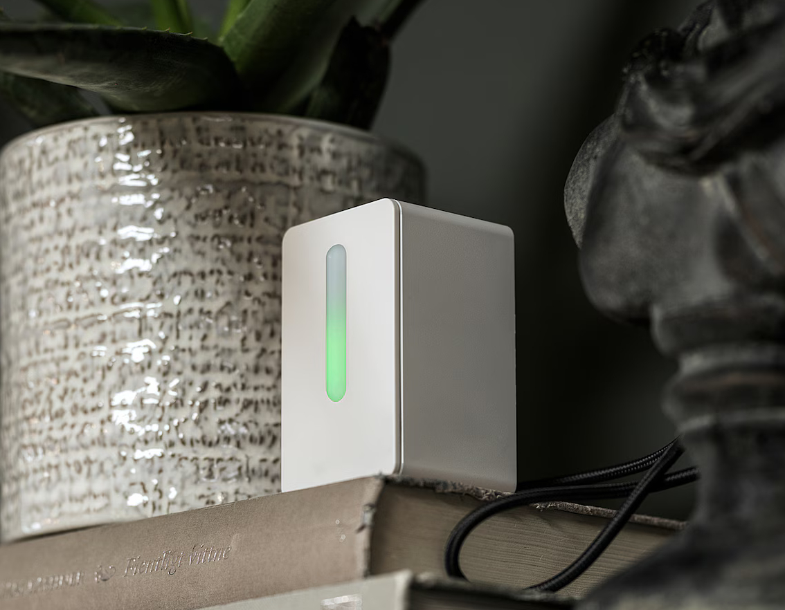
On a trip to my local IKEA for some other project supplies, I happened upon an intriguing item, a Vindriktning air quality sensor. Unlike its big brother, the ZigBee enabled Vindstyrka, it is a relatively simple box, with just a few diffuse LEDs on the front, indicating the “air quality” of a room. In its stock form, its really that simple. It piqued my curiosity as I wondered what metrics it used to determine the local air quality, and more importantly, if it could be hacked.

Cropped from this image from IKEAs website
Hacking the Vindriktning
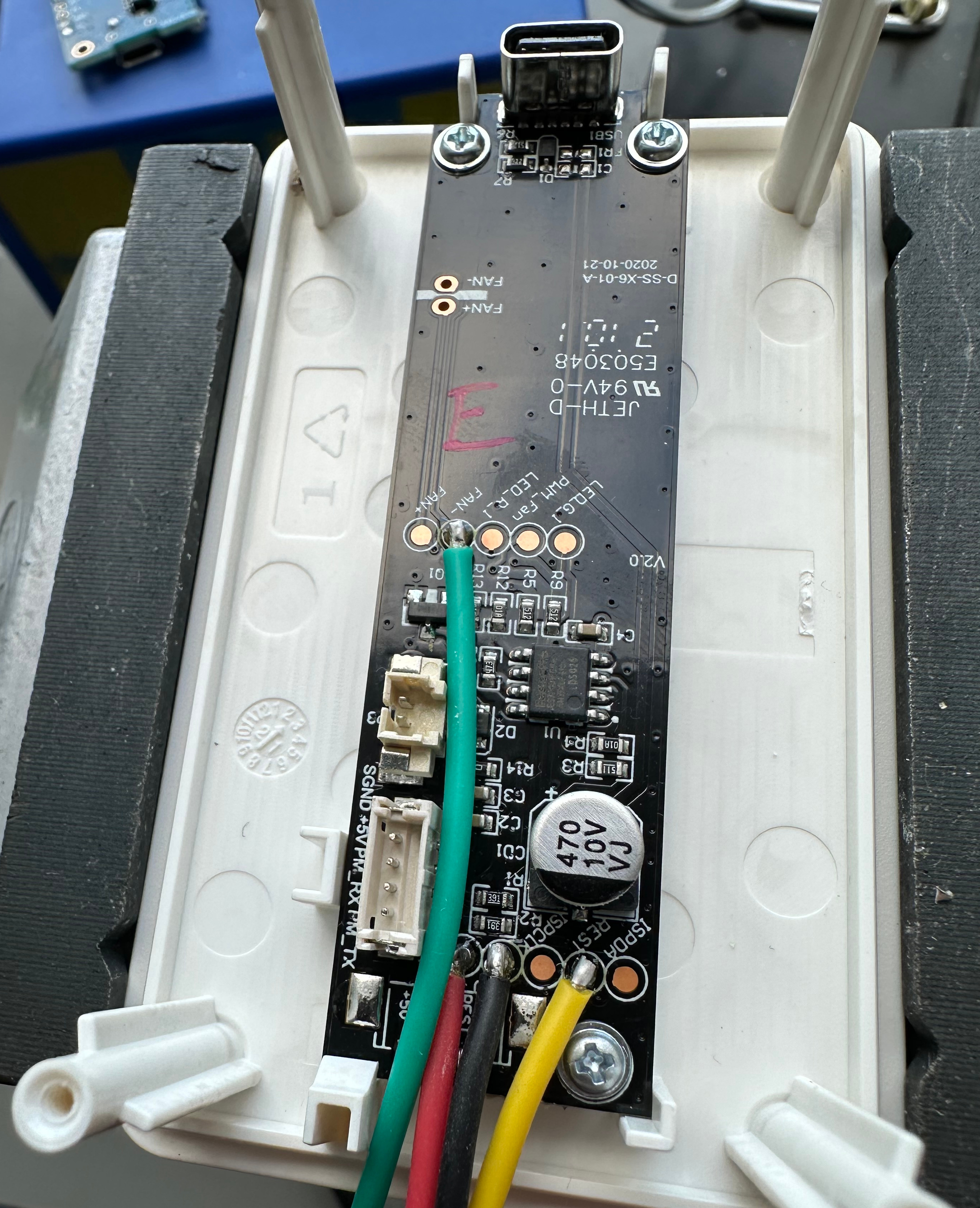
Upon getting it home and cracking the shell, I was pleased to find that the included PM2.5 sensor seemed to use UART to communicate with the motherboard. This was good news, as it would make it easy to pass the signal from the TX pin of the sensor to an ESP board, without interrupting the function of the rest of the device. Being powered by a USB-C port on the rear, I suspected it used 5v, a fact that was easy enough to confirm after some poking with a multimeter. This was also good news, as it would make powering an ESP without cutting holes in the case. Even better, there were some large solder pads that could be used to make the connection not just for the 5v and ground connections, but also communications from the particle sensor.

The particle sensor, unlike the other I had previously used, does not include its own fan. Instead, an external fan is used, which is connected to the motherboard separately to the sensor, and is enabled only when the sensor is taking a reading. This provides an opportunity for us, as we can listen for the fan being powered to inform us when a reading is being taken. This could prove useful, as we have no control over the sampling frequency. Fortunately for us, there is a handy solder pad available on the ground lead of the fan.
The downside of these units is their simplicity. They can detect only the particulate matter in the air, having no ability to detect other properties such as temperature, pressure, humidity, CO₂, and VOC levels. Fortunately, the enclosure is relatively spacious, and as I was planning to use an ESP board, adding in sensing for these properties would be relatively simple.
There are plenty of available sensors to choose from. I set myself a £50 budget for the project, including the original £15 the Vindriktning cost. This meant that sensor prices had to be kept low. I figured a good place to start would be to pick a temperature and humidity sensor. I have previous experience with the ASAir DHT22 (as well as the DHT11, though I discounted that for its poor performance at below freezing given I would like to create a version of this sensor package for use in outdoor sensors) but decided instead to use the ubiquitous Bosch BME280 (importantly, if you’re shopping for parts to build one of your own, not the BMP280 which lacks humidity sensing) due to its inclusion of a barometric pressure sensor, removing the requirement to add a separate sensor just for this. The BME280 communicates over I2C, which is ideal when adding multiple sensors as it simplifies the wiring greatly. Having crossed off the above values in a single sensor, I was now missing only a way of sensing CO₂ and VOC levels. The obvious choice for this project was the AMS CCS811. It is compact, reasonable cheap when compared to other alternatives, and measures VOC levels, and provides an estimated CO₂ (eCO₂) level that is more than accurate enough for what I needed.
The last step was to select a microcontroller. I had already decided that this should be from the ESP family, as it would allow me to use ESPHome to connect the sensors to Home Assistant. Happily, I had a spare esp8266 based Wemos D1 mini from a previous project. Not only that, but it fitted perfectly into the Vindriktnings case.
I wrote a simple config in ESPHome to expose the sensors to home assistant as individual entities, and flashed it to the D1, soldered up the connections to the sensors, shut the enclosure, and powered it on. I was very happy to see it connect straight away and begin outputting data.
It was simple to create a HASS dashboard to graph the outputs. In the future, I will look at using the data to control various actions such as turning on an air purifier
The IKESP-Air Project is Born
Upon chatting to a few friends, it turns out they already owned a few of these boxes between them, and were interested in upgrading them in the same way I had. I decided I was more than happy to do that, and that it would be a fun project. The first challenge was to figure out the software. I had never distributed an ESPHome device to anyone else previously. Flashing them with the same code as my own would be unwise, as they would be neither adopted by their ESPHome instance, nor connected to their WiFi.
Solving the latter was easy, as ESPHome allows you to have devices broadcast a WiFi network should they fail to connect to your WiFi within 60s of boot. It then uses a captive portal to allow you to connect the ESP device to a new network. This is intended, in this form, to allow you to reconnect devices following a change in SSID or password, without having to reflash the devices.
Solving the former was a little more of a challenge, however thanks to this excellent guide it was made much simpler. By adding the below to the ESPHome device yaml, it allows you to send a device to a person, have them connect it to their network, and adopt it into their ESPHome instance. ESPHome will then download the yaml file from the specified GitHub repo, allowing the end user to modify it as they see fit.
esphome:
  project:  # This provides the ESPHome project information, which is exposed through the logs and device_info response
    name: IKESP.IKESP-Air
    version: dev

wifi:   # This allows the device to broadcast an AP for to allow configuration
  ap:
    ssid: "ssid"
    password: "password"

dashboard_import:   # This imports the specified yaml file to the users ESPHome instance
  package_import_url: github://GitUser/GitRepo/example.yaml@branch
  import_full_config: True  # If this is set to false, then ESPHome will only reference the config, and will not allow end users to modify it
The process of connecting the device to the end users ESPHome instance is as simple as:
- Power on device and connect to device AP
- Connect device to your WiFi SSID using the captive portal
- Adopt the newly reported device in ESPHome and allow it to flash the full firmware
- (Optional but recommended) Configure encryption
As I post this, the flashed devices are winging their way to the friends that asked for them. If there are any issues when they are received, I’ll make sure to update this post.